 |
| Integrated circuit 555 timer |
IC 555 timer tutorial , Pin diagram, Circuit, working principle :
In today’s topic, we will present to you an educational article about the so-called integrated circuits (ICs), especially the 555 circuit or timer, which is considered the most famous integrated circuit in the field of electronics. So how does the 555 timer work? And an explanation of the various terminals ( pins) and components of the timer 555? The most important uses of timer 555? Block diagram?
Definition of integrated circuit timer 555 :
The timer 555 or timer 555 is a small chip that contains eight terminals and is often made of silicon.
It contains inside it many electronic components such as transistors, resistors, and capacitors that are very precise and connected to each other, forming a loop that does not have a beginning or end, That's why it's called an integrated circuit, and the 555 timer is very similar to the Optocoupler in terms of shape only.
Note :
To be exact Timer 555 contains 25 transistor, 2 diodes and 15 resistors.
Components of the integrated circuit 555 timer:
The timer 555 timer consists of eight terminals and each end has a specific role in the construction of electronic circuits:
 |
| IC timer 555 pins |
1: GND pin.
2: Trigger pin.
3 : Output.
4 : Reset.
5 : Vcc pin.
6 : Discharge pin.
7 : Threshold pin.
8 :Voltage Control.
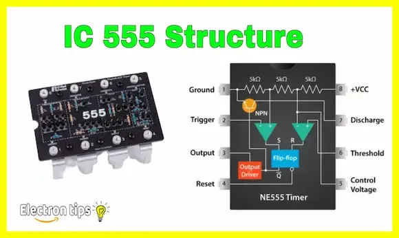
Timer 555 Structure:
This following image showing IC 555 timer structure.
 |
| IC timer 555 structure |
How do we know the pins of the 555 timer :
If you notice carefully, the back of the timer 555 or all integrated circuits contains a small hole or dot, and this point to its left begins to number the tips of the timer from one to eight counterclockwise. Companies place this hole or dot to make it easier for us to know the tips of the timer 555 and other integrated circuits.
As for the 555 timer, it always contains the number 555 on the back, or NE555, which allows us to distinguish it from other integrated circuits, as most integrated circuits are similar to each other, but may differ from one manufacturer to another, and this table shows you all types of designations for the 555 timer, From the various manufacturers of this amazing electronic component:
 |
| IC timer 555 manufacturing company |
Why is the timer called 555 timer :
 |
| Why is the timer called 555 timer |
IC Timer 555 oscillators modes :
The timer 555 can produce multiple oscillators, Astable mode , mono-stable mode and bistable mode , and each oscillator has a specific electronic circuit :
Timer 555 Astable mode:
In astable mode, it generates a continuous square wave output, here is a simple Astable mode oscillator circuit using IC timer 555 :
 |
| Timer 555 Astable mode |
Timer 555 mono-stable mode:
monostable mode is used to create a pulse of a specified duration (a one-shot pulse) in response to an external trigger. Here's Monostable oscillator circuit using timer 555 :
 |
| Timer 555 mono-stable mode |
Timer 555 bistable mode:
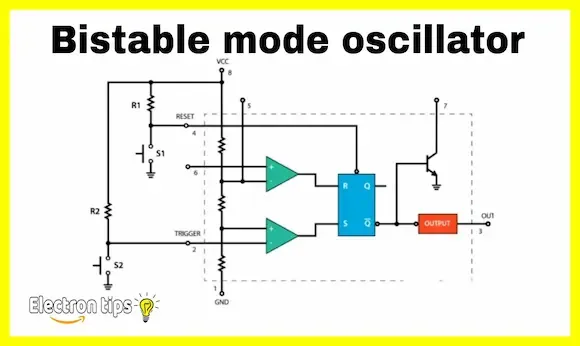
In a bistable mode the 555 timer operates as a flip-flop, allowing it to hold one of two stable states indefinitely until triggered to change, that's a bistable oscillator circuit using a 555 timer:
 |
| Timer 555 bistable mode |
IC timer 555 Applications:
The 555 IC timer has many uses, as most, if not all, electronic devices contain the 555 integrated circuit, laptop computers, smart phones, televisions, and it is also found in most home electrical appliances such as the microwave oven and refrigerators. It is also used In many electronic circuits, such as the light sensor circuit, this is done by connecting it to a photoresistor (LDR).
The 555 integrated circuit or timer is used to obtain a negative current.
Conclusion:
Finally, this was a comprehensive topic about the integrated circuit or timer 555 , if you have any questions with this topic you can ask me in the comments section or in own Facebook page " electrical engineering tips ".
